Control Bar and Status Bar
The Control Bar is located at the top of the Figure Window, and allows you to control the Figure Window's operating environment. The Status Bar is located at the bottom of the Figure Window, and shows the current coordinates of the cursor in 3D space, allows you to change the units used, and displays other information.
Control Bar
Select View > Control Bar to toggle the display of the Control Bar.
The buttons displayed on the Control Bar can be customized by first right-clicking (Windows) or Control-clicking (Mac OS) on an empty area of the Control Bar, and then selecting Hide, Icon, Text, or Icon+Text.
 Editing Mode
- Click to switch between object editing modes. The editing modes are Object, Modify, Mapping, Joint, and IK. Switch editing modes as needed when doing different work in your scene. The Figure Window updates to show controls for the selected mode.
 Still/Sequence Mode
- Click to select Still Mode (used when working with regular still images) or Sequence Mode (which updates the Figure Window with the state of Motion Window's sequence cursor).
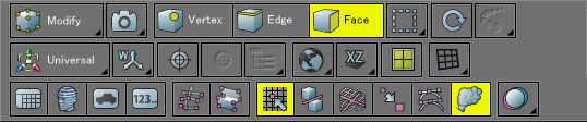
- Mesh Editing Mode Buttons
- In Modify Mode, use the Mesh Editing Mode buttons to switch between methods of selecting different elements of a polygon mesh. From left, the buttons are Vertex Selection Mode, Edge Selection Mode, and Face Selection Mode.
 Vertex Selection Mode
- In Vertex Selection Mode, clicking or dragging across a polygon mesh will select its vertices (points).
 Edge Selection Mode
- In Edge Selection Mode, clicking or dragging across a polygon mesh will select its edges.
 Face Selection Mode
- In Face Selection Mode, clicking or dragging across a polygon mesh will select its faces (polygons).
 Selection Mode
- Click to switch between Figure Window selection modes. There are three modes: Box, Lasso, and Trace. Select a mode according to the kind of selection you wish to make.
 Continuous Mode
- Continuous Mode enables you to use the selected tool repeatedly, without reselecting the tool each time.
 Repeat
- Used to repeat an operation performed last using the Move/Copy tool the number of times specified. Click the Repeat button and select the number of times to repeat from the pop-up menu. To repeat a number of times not on the menu, select "..."
 Manipulator Types
- Click to switch between manipulator types. Select Universal, Translate, Scale, Rotate, Size, or select Hide to hide the manipulator.
By default, the universal manipulator is displayed in all views.  Manipulator Coordinate Mode
- Click to change coordinate systems used for the manipulator. Select User, World, Local (Default Rotation), Local, or Normal.
- Manipulator Pivot Settings
- The following two buttons affect the 3D Manipulator. From left, these are Set Pivot, Reset Pivot, and IK Depth.
 Set Pivot
- Click this button and then click in the Figure Window to set a new position for the origin of the 3D Manipulator.
 Reset Pivot
- Resets the 3D Manipulator's origin to the default position.
- NURBS Assembly Settings (Shade3D Professional)
- The following two buttons are used for CAD assemblies. For details on assemblies, see Surface Assembly.
 Set Assembly Origin
- Click to set the assembly origin of a NURBS surface.
 Assembly
- Click to assemble two selected NURBS surfaces after setting the assembly origin for each.
 IK Depth
- Click to select the level of hierarchy depth for which IK is effective when working with joints in IK Mode.
 Coordinate System
- Click to switch between global and local coordinate systems. The global coordinate system is the default.
 Work Plane
- Click to switch between work planes. A work plane is used to constrain movement of the 3D cursor in a particular plane in Perspective View.
 Viewport Layout
- There are nine different viewport layouts for the Figure Window. Click this button to open the Viewport Layout Controller, and position the mouse pointer over it so that the red rectangle contains the viewports you wish to display.
 Wireframe Color
- Click to specify the way color is added to wireframes in the Figure Window.
- Window Open Buttons
-
 ShadeExplorer
- Opens or closes the ShadeExplorer window. For details see ShadeExplorer.
 3D Printing Assistant
- Opens or closes the 3D Printing Assistant. For details see 3D Printing Assistant.
 Template Settings
- Opens or closes the Template Settings Window. For details see Template Settings Window.
 Numeric Input
- Opens or closes the Numeric Dialog. For details see Numeric Input Dialog.
- Sketch/Photo Modeling Buttons
-
 Sketch Modeling
- Opens or closes the Sketch Modeling Window. For details see Sketch Modeling.
 Photo Modeling
- Opens or closes the Photo Modeling Window. For details see Photo Modeling.
- Other Figure Window Settings
- From left: Snap to Grid, Object Guide, Large Cursor, Large Point, Multi-Handle, Particle Preview, and Stereo Vision.
 Snap to Grid
- Snaps the 3D cursor to the grid and in-between the grid at 1/2 width.
Note Snap to Grid and Object Guide cannot be used at the same time.
 Object Snap
- When creating or manipulating objects, snaps the 3D cursor to object points, edges, and the center of bounding boxes. For details see Object Snap.
Note Snap to Grid and Object Snap cannot be used at the same time.
 Large Cursor
- Extends the crosshairs of the 3D cursor to fill each viewport.
 Large Point
- Control points are displayed larger.
 Multi-Handle
- In Modify Mode, when multiple control points are selected, their tangent handles can be edited simultaneously.
 Particle Preview
- Enables a real-time preview of Particle Physics (Shade3D Standard and Professional).
 Stereo Vision
- Click to select the type of Stereo Vision used in the Figure Window: None, Anaglyph, Nvidia 3D Vision, Polarized 3D Display, or Polarized 3D Display (Reversed).
Nvidia 3D Vision makes it possible to display Stereo Vision in full color but requires a compatible display.See also Polarized 3D Display
Status Bar
Select View > Status Bar to toggle the display of the Status Bar.

- 3D Coordinates
- The current X, Y, and Z coordinate values of the 3D cursor are displayed.
- Distance
- Depending on whether Absolute or Relative is selected from the Relative pop-up menu, the distance in a straight line to the 3D cursor from the origin or from the last-clicked position is displayed.
- Relative Pop-up Menu
- Switches between measuring the distance to the 3D cursor from the origin (Absolute) or from the last-clicked position (Relative).
- Dot
- The distance between adjacent dots on the monitor. A dot is the minimum unit of distance the mouse pointer can move. If the Figure Window units are set to "mm", a Dot value of 10 indicates that the dot distance is 10 mm. This means that the mouse pointer can move in units of 10 mm.
- Grid
- The distance represented by a single grid cell in the Figure Window.
- Units Pop-up Menu
- Specifies the units used in the Figure Window. Choose between mm, cm, m, km, inch, foot, yard and mile.