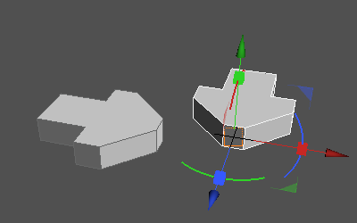
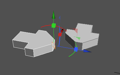
Surface Assembly
The assembly origin of a NURBS surface can be set, allowing you to join it with the origin of another surface.
Assemblies in Shade3D are done in two basic steps: specifying the assembly origin of each component or part, and positioning the components in relation to each other.
An assembly origin is shown by the 3D Manipulator. Its position and orientation can be specified according to the requirements of the assembly.
The up vector of the assembly origin of one surface will be aligned with that of the second surface, creating a coincident mate.
| Basic | Standard | Professional |
|---|---|---|
| - | - | O |
Usage
Setting the Assembly Origin
- Prepare the two parts or components to assemble, and select one.

- From the Control Bar, click the Assembly Origin button.

- Click a point for the origin, such as an end point, curve, center, face, or face center. In the below figure, the face center has been clicked. (Object Snap is turned on automatically.)

- The assembly origin (the point to join) is set at the point clicked. This point can be moved or oriented differently. Fine adjustments can also be made in the Tool Parameters.

- Click Apply in the Tool Parameters to set the assembly origin for the first part.

- Now set the assembly origin of the second part in the same way.


Positioning the Assembly
- Select both parts with assembly origins set.
First select the main part that will remain in place, and then add the second part to the selection by holding down Ctrl (Win) or Command (Mac).

- From the Control Bar, click the Assembly button.

- In the Tool Parameters, select Coincident to align the assembly origin of the second object (part) to the assembly origin of the first.
The angle and distance of the alignment can be adjusted to fine-tune the assembly.


- Click Apply to finish the assembly.

Tool Parameters (Set Assembly Origin)

- Offset
- Specifies the distance to offset the assembly origin from the clicked position or previously set position.
- Fixed Direction
- Fixes the orientation of the assembly origin, allowing only movement.
- Reset Rotation
- Resets the assembly origin axis to match global coordinates.
- Reset
- Resets the position of the assembly origin, allowing you to specify a new point by clicking in the Figure Window.
- Apply
- Applies the assembly origin to the specified position.
Tool Parameters (Assembly)

- Coincident
- The components are positioned so their assembly origins are aligned together with the up vectors facing each other.


- Parallel
- The components are oriented so the up vectors of their assembly origins face each other, but are not moved together.


- Angle Text Box
- Specifies the angle to rotate the parts relative to each other, using the assembly origin up vector as the axis.


- Distance
- Specifies the distance to separate the assembly origins from each other.


- Flip Alignment
- Reverses the alignment so that the up vector of each assembly origin is pointing in the same direction.


- When unselected, the up vectors will be aligned facing each other (pointing in opposite directions).

- Apply
- Applies the assembly.
- Cancel
- Cancels the assembly.
Note Available in Shade3D Professional.