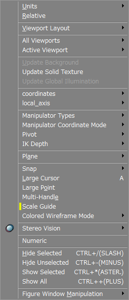
Figure Menu
This menu mainly contains settings for Figure Window display settings. Most of the tools in the Figure menu can also be accessed from the View Display pop-up menu of each Viewport or from the Control Bar.
For details on the View Display pop-up menu, refer to Parts of the Shade3D Interface. For details on the Control Bar, refer to the section on the Control Bar and Status Bar.

- Units
- Specifies the units of scale used in the Figure Window. Choose between cm, m, km, inch, foot, yard and mile.
- Relative
- When selected, the Status Bar displays the relative distance from the last clicked point.
- Viewport Layout
- For the Figure Window layout, select between Top Left, Bottom Left, Top Right, Bottom Right, Top, Bottom, Left, Right, or Shared.
- All Viewports
- This submenu allows you to switch display modes for all viewports.
- Active Viewport
- This submenu allows you to switch display modes for just the active viewport.
- Update Background
- Updates the background and redraws the Figure Window.
- Update Solid Texture
- Updates solid textures and redraws the Figure Window.
- Update Global Illumination
- Recalculates Global Illumination (G.I.) and updates the Figure Window.
- Coordinate System
- Switches the coordinate system used in the Figure Window.
- Local Axis
- Set the local coordinate axes.
- Manipulator Types
- This submenu allows you to select the type of 3D Manipulator to use: Universal, Translate, Scale, Rotate, Shear, or Size. Select Hide to hide the manipulator.
- Manipulator Coordinate Mode
- This submenu allows you to select the type of coordinate system to use with the 3D Manipulator: User, World, Local (Default Rotation), Local, or Normal.
- Pivot
- Set or reset the origin of the 3D Manipulator.
- IK Depth
- This submenu allows you to select an IK Depth of between 1 and 9 when using IK.
- Work Plane
- This submenu allows you to select the plane in which the cursor moves. Choose between YZ, XZ, XY, Screen, and Auto.
- Snap
- This submenu allows you to select how snap works.Object Guide settings can also be selected here.
- Measure
- Opens the Measure tool, used to measure the distance and angle between two points in 3D space. For a detailed description see Measure Tool.
- Enter Coordinates...
- Opens a dialog in which you can enter numeric coordinate values to create a line object.
- Perspective View Grid Settings
- Opens a dialog box for changing the grid settings of the perspective view. For a detailed description see Customizing the Perspective View Grid.
- Large Cursor
- When selected, the 3D cursor crosshairs extend to the borders of the Figure Window.
- Large Point
- When selected, vertices and control points are displayed larger.
- Multi-Handle
- When selected, multiple selected control points can be manipulated simultaneously.
- Scale Guide
- When selected, a guide showing the approximate scale is displayed when zooming in the Figure Window.
- Colored Wireframe Mode
- This submenu allows you to select the appearance of the wireframes. Choose between Uncolored Wire, Colored Wire (Non-Modify Mode Only), Colored Wire, Marker Color (Non-Modify Mode Only), and Marker Color.
- Stereo Vision
- This submenu allows you to select the type of Stereo Vision used: None, Anaglyph, Polarized 3D Display, or Polarized 3D Display (Reversed).
- Hide Selected
- Hides the selected shapes in the Figure Window.
- Hide Unselected
- Hides the unselected shapes in the Figure Window.
- Show Selected
- Shows the selected shapes in the Figure Window.
- Show All
- Shows all shapes in the Figure Window.
- Figure Window Manipulation
- This submenu allows you to manipulate the Figure Window view using Zoom In, Scroll, and more.