Sketch Modeling Reference
Basic Settings Tab
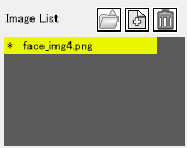
- Image List
- This list allows you to manage images used for generating 3D information. Open, Save and Delete images. Images that have associated camera information show a * next to them.

- Sketch Modeling Output Options
- Specifies the size of objects saved. The size is based on the bounding box that contains the object.

- Error Margin
- This shows the average distance between vertices of the generated 3D lines and vertices of the 2D lines. A smaller value indicates a smaller degree of error. A large value may mean the sketch image is not suitable for Photo Modeling or the 2D lines are not placed correctly.

- Auto Update
- When Auto Update is selected, settings are automatically saved to custom attributes of the part whenever you finish creating a 2D line or generating 3D lines.
 Save to Shade3D Button
- Saves information in custom attributes of the part.
 Load from Shade3D Button
- Loads information from custom attributes of the part into the Sketch Modeling editor.
Modeling Tab
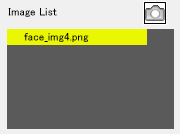
- Image List
- Lists the sketch images. These images can be used as templates. Click the Snapshot button to save the current preview as a master surface.

- Create/Modify Tools
-
 Line Button
- Use the Line button to create 2D line objects or to select 2D lines, 3D lines or 3D faces. Shift-click to select multiple lines. Select and drag to move 2D lines.
The Line Thickness option is available when the Line Button is selected.  Point Button
- Use the Point button to click to select vertices. Shift-click to select more than one vertex. Select and drag vertices to move.
The Line Thickness option is available when the Point Button is selected.  Select All Button
- Select all 2D lines, 3D lines and 3D faces in the preview area.
 Undo Button
- Undo up to 100 processes.
 Redo Button
- This button re-implements a process that was previously undone with the Undo Button.
 P-line Button
- Click in the preview area to place vertices for a new 2D line. Press Enter, double-click or click the Confirm Button to complete the placement.
 Spline Button
- The Spline Button gives access to the Spline Settings options, which allows you to increase the number of points in a 2D line, creating a 2D line with smooth curves.

- Enter the number of vertices to change in the Division Box and click the Confirm Button to change.

- (Division Box Options: Change from 4 to 12)
 Add Point Button
- Click on a 2D line to add vertices.
 Delete Point Button
- Click to delete vertices from a 2D line.
 Delete Button
- This button deletes selected 2D lines, 3D lines and 3D faces.
 Reverse Vertex Order Button
- This button reverses the order of the vertices of the selected 2D line.
 Snap Button
- You can snap placement of 2D lines, movement of 2D and 3D lines and creation of 3D faces and moving of 2D and 3D lines.
 Symmetry Button
- When this option is selected, it applies symmetry rules to the placement of 3D lines when you use the Generate 3D button.
 Axis Button
- Displays XYZ axis and XZ plane after generating 3D within a grid reference. Set the color of the XYZ axes in Shade3D Preferences.
 Info Button
- When selecting a 2D line, displays the number of vertices.

 Face Button
- Creates triangular 3D faces by clicking three vertices on a 3D line. The Create Face Option is displayed in this mode.
- Auto Recognize Center Line Checkbox
- This option is only available after generating 3D lines. When selected, a placed 2D line is treated as the center line using an internal recognition system. When it is off, it does not automatically recognize a central line.
- Auto recognize follows specific rules.
- If there are only two 2D lines with the same number of vertexes, Sketch Modeling treats them as symmetrical lines when the Generate 3D button is pushed.
- If there is only one 2D line, it becomes a central line when you use the Generate 3D button.
- You should use this feature when automatic recognition doesn't correctly identify the 2D line you want to use as the center line. Misrecognition can happen when there are many 2D lines, or there are several 2D lines with the same number of vertexes placed close together.
- Confirm Button
- Click this button to confirm 2D lines created with Pline or divisions created with the Spline Button.
- Generate 3D Button
- Generates 3D lines from the 2D lines placed in the Preview area. If you get an error message, the 2D lines may not meet Sketch Modeling's requirements for number of vertices and line types. Adjust the 2D lines and try again.
- Set Center Line Button
- This option only works if you have already generated 3D lines. Select a 2D line in the Preview area and then click this button to set it as the center line.
- Focal Length Options
- This sets up the vertical field of view that is used in the 3D view. When focal length is set low, the field of view widens. This is used to adjust distortion in 3D generation.
- Transparency Options
- This adjusts the transparency of the loaded image. At 1.0, the loaded image is completely transparent.
- Line Thickness
- Available when Line, Point, P-Line or Add Point are selected. This sets the thickness of the lines on a scale of one to four.

- Create Face Group
- This is displayed when Face is active in the Create/Modify Group. The Transparency Slider sets the transparency of faces with 1.0 being completely transparent.

View Group
Change the appearance of the Preview area by clicking and dragging the icons directly.
 Pan Button
- This scrolls the preview area up, down, left and right. Alternatively, pan using the arrow keys, or press Space and drag.
 Zoom Button
- This zooms the preview area. Alternatively, zoom using the mouse wheel.
 Rotate Image Button
- This button rotates the loaded image.
 Rotate Object Button
- This button rotates 3D lines in the preview area.
 Reset Button
- This button resets the preview area to the default position.