Line Offset
An offset line object can be created from either a line object or a curved surface. If a curved surface is selected, an offset curved surface will be created.
Usage
- Selecting Line Offset
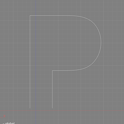
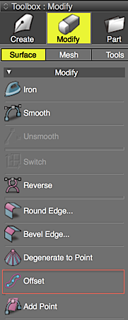
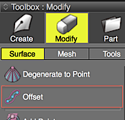
- Select Tools > Modify > Offset. Offset is also available from the Toolbox by selecting Modify > Surface > Offset.
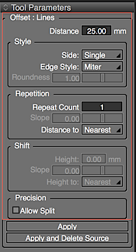
- Adjust the settings in Tool Parameters as needed.
- Create the offset line object by clicking and dragging in the appropriate Viewport of the Figure Window.
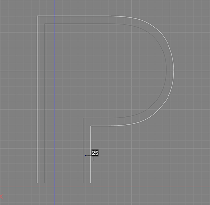
- In the Tool Parameters select Apply or Apply and Delete Source. Alternatively, press the Return key.
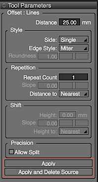
Note Before selecting Apply, the Offset settings may be modified in the Tool Parameters.
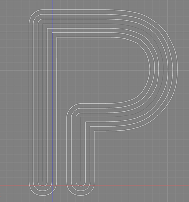
Curved Surface Offset
- Select a curved surface.
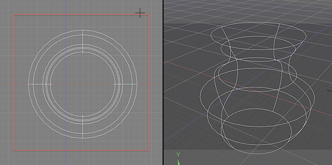
- From the Menu Bar, select Tools > Modify > Offset. Offset is also available from the Toolbox, under Modify > Surface > Offset.
- Create the offset curved surface by clicking and dragging in the appropriate Viewport of the Figure Window.
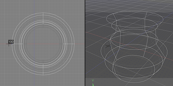
- Adjust the settings in Tool Parameters as needed.
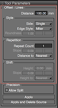
- In the Tool Parameters select Apply or Apply and Delete Source. Alternatively, press the Return key.
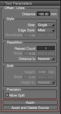
Note The curved surface is offset using a front projection in the clicked viewport.
Offset Tool Parameters
- Distance
- Sets the offset distance.
- Direction
- Select either Single or Dual for the sides to offset.
- Count
- The number of times to do the Offset operation.
- Slope
- The offset distance ratio. Enabled when Count is set to 2 or more.
- Distance to
- Select Nearest Line or Farthest Line for the Offset Distance display. Enabled when Count is set to 2 or more.
- The height
- Sets the offset height of the distance.
- Slope
- Sets the offset height ratio.
- Height to
- Select Nearest Line or Farthest Line for the Offset Height distance.
- Allow Split
- When enabled, control points are appended to the offset line object, improving the precision of the curve.
Using Scripts to Create Offset Line Objects.
From the Script Window check Record, and then create an offset line object from the Toolbox. A script will be recorded.
- Example: xshade.scene().create_offset_lines(200.0, [0, 1, 0], 0, 2, 1.2, 2, 0.1, 0, 10, 0.3, 0, True, False)
-
Arguments :
string : optional : If omitted, the default name is used
Arguments :
float : Distance
Arguments :
vec3 : The direction cosine of the coordinate system : [0,1,0] : The XZ plane, [0,0,1] : The XY plane, [1,0,0] : The ZY plane
Arguments :
int : The Offset direction : -1 : Single-sided (counter-clockwise), 0 : Double-sided, 1 : Single-sided (clockwise)
Arguments :
int : Edge Style : 0 : Miter, 1 : Bevel, 2 : Round 1, 3 : Round 2
Arguments :
int : Roundness : between -1 and 3.0
Arguments :
int : Count
Arguments :
int : The Distance Slope : between -1.0 and 1.0
Arguments :
int : The spacing type : 0 : Nearest Line, 1 : Farthest Line
Arguments :
float : The Height when repeating
Arguments :
int : The Height Slope : between -1.0 and 1.0
Arguments :
int : The spacing type : 0 : Nearest Line, 1 : Farthest Line
Arguments :
bool : Allow Split (appending control points) : True : allow, False : do not allow
Arguments :
bool : Delete original shape : True : Delete, False : Do not delete