Using Bones
Creating Bones
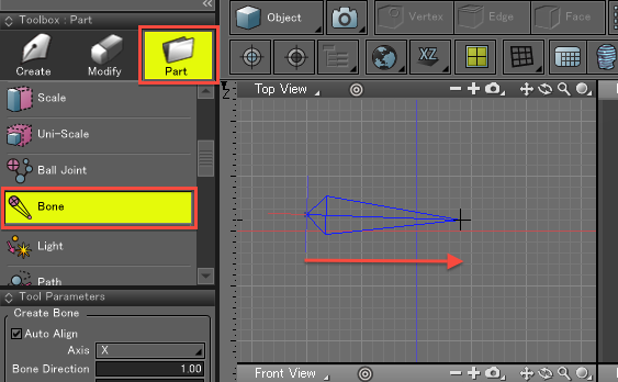
- In the Toolbox, select Part > Bone to display the Tool Parameters for creating a bone.
With Bone selected in the Toolbox, click and drag in the Figure Window to create a bone.
Newly-created bones have two bone objects, a start point and an end point, as can be seen in the Browser.
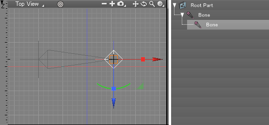
- Next create a second bone. If a Bone object is selected in the Browser when creating a new bone, it will be used as the start point for the new bone. The point where the mouse button is released after the click-and-drag operation becomes the end point.
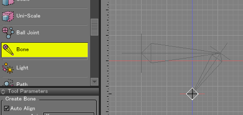
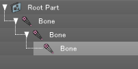
If a Bone object is not selected in the Browser when creating a new bone, two new Bone objects will be created, one each for the start and end points of the click-and-drag operation.
- By selecting a Bone object that already has a child Bone part before creating a new bone, it is possible to place a branched bone.
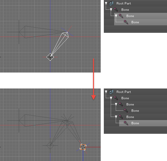
About Bone Branches
- In the case of ball joints, by placing two child ball joints below a parent ball joint it is possible to create a structure with two branches.
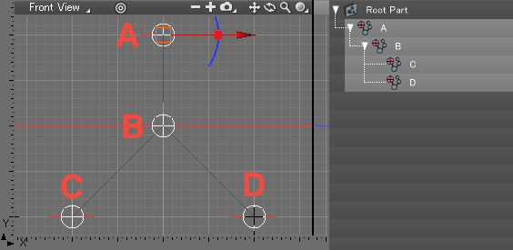
With bones a similar structure is also possible, but because the direction of movement is controlled by two Bone objects, the branched part is copied, resulting in two identical parts, as shown below.
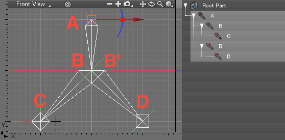
This way it is possible to conform the orientation of each Bone to the specified axis (the X axis by default) in local coordinates.
Changing the Direction of Movement Axis
- Bone settings can be modified in the Object Info Window.
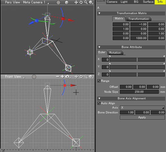
From the Control Bar, change the Manipulator Coordinate Mode to Local, and by default the bone's direction of movement is aligned with the X axis.
Select an applicable Bone object in the Browser, and under the Bone Axis Alignment group in the Object Info Window, select X, Y, or Z from the Axis pop-up menu and click the Apply Button in order to change the direction of movement axis of the bone.
Modifying the Node Size
- The Node Size is automatically assigned based on the distance between the start and end points when a new bone is created.
The Node Size parameter, under the Bone Joint Attributes group of the Object Info Window, can be used to modify this value.
Bone Angle Limits
- Minimum and maximum limits on the angles of movement can be specified for bones along each XYZ axis, in local coordinates.
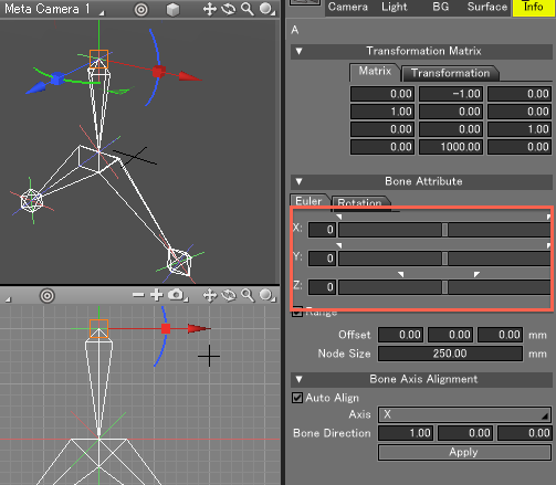
In the Object Window, under the Bone Attribute group, select the Euler tab and slide the white triangles to modify the minimum and maximum angles for each XYZ axis.
By deselecting the Range Checkbox below the sliders, the bone angle limits are disabled.
Because the default direction of movement is the X axis, the X axis is the axis along which the bone rotates (twists).
When using angle limits, pay attention to the rotational limits of the joint.
When rotating bones in the Figure Window in Object Mode, the position of the actual bones changes, and is independent of rotational elements of the joints.


