Multi-Layer UV Mapping Using Face Groups
Multiple UV layers can be created and used together with Face Groups to do multi-layer UV mapping.
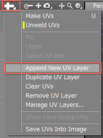
- Select a polygon mesh, and select Append New UV Layer from the UV Menu in the UV View.
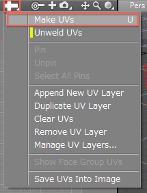
- Select Make UVs from the UV Menu.
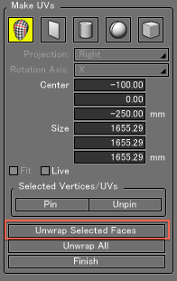
- Select some faces of the polygon mesh and click Unwrap Selected Faces in the Tool Parameters.
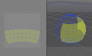
- Next select Save UVs Into Image from the UV Menu to export the UV map as an image, and add color.
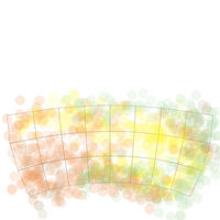
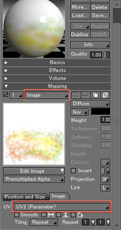
- Create a master surface and load the image in the Mapping option group of the Surface Window. At the bottom of the Mapping option group, on the Image tab, select the appropriate UV layer.
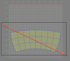
- Select the polygon mesh.If it is unselected, select it again in the UV View.
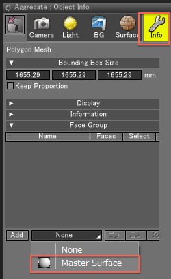
- In the Object Info Window, under Face Group, select the master surface you created from the master surface pop-up menu.
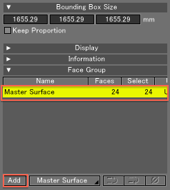
- Click the Add button to add the Face Group.
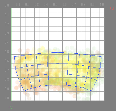
- From the View Display menu in the UV View, select Show Mapped Image to confirm that the master surface image is assigned.
- Continue by assigning master surfaces to each additional Face Group of the polygon mesh.
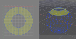
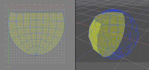
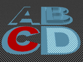
- Render the polygon to see the results of the multi-layer UV mapping.
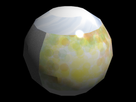
Relationships Between Face Groups, UV Layers and Master Surfaces
UV layers and Face Groups have a one-to-one relationship.
UV layers specified for a master surface will apply to all polygon meshes using that master surface.
The below figure shows Face Groups set to two different polygon meshes.
Faces A, B, C and D of the polygon meshes are each unwrapped to UV layers 1 to 4, and master surfaces A, B, C and D are assigned to each.
The UV layers of polygon mesh A are assigned master surfaces A, B, C and D, in that order. The UV layers of polygon mesh B are assigned master surfaces D, C, B and A, in that order.
Master surface A is assigned to the first UV layer, master surface B is assigned to the second UV layer, and so on.
As a result, the faces of polygon mesh A match the letter of each texture, while the textures of polygon mesh B are reversed.
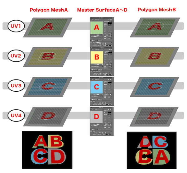
If images A, B, C and D in a single master surface are assigned to mapping layers 1, 2, 3 and 4 with a Diffuse Weight of 1.0, the mapping image in the top layer is rendered.
