Bevel Settings
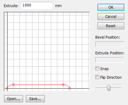
Clicking the Set button shows the Bevel Settings dialog, which allows you to configure the bevel settings.
Bevel Settings Dialog
You can edit the bevel line on the dialog.
| Bevel Settings |
|---|
|
- Extrude
- It is defaulted to show the value specified in the Extrude text box of TextEffector. You can modify the value in the text box.
- OK Button
- Click this button to finish configuring the bevel settings and close the dialog.
- Cancel Button
- Click this button to cancel configuring the bevel settings and close the dialog. The bevel line settings you configured are discarded.
- Reset Button
- Click this button to restore the initial bevel settings. The bevel line settings you configured are discarded.
- Bevel Position and Extrude Position Display Boxes
- The boxes show the coordinate of a control point or line handle when the cursor is on it. The boxes also show the coordinate of a control point or line handle when the mouse pointer is dragging it. The Bevel Position indicates the position in the vertical direction, the Extrude Position indicates the position in the horizontal direction, and the bevel fixed point at lower left side of the Bevel Settings dialog is the origin.
- Snap
- Turn it on to snap the control points to the grid in the bevel line editing area. The points are snapped to the intersection points and middle points of the intersections on the grid.
- Flip Direction Checkbox
- Some fonts may ended up with the bevel direction reversed (concave, as opposed to the normal covex bevel). Check the Flip Direction checkbox for such a font. The bevel line is inverted vertically.
- Editing Area Adjustment
- Use this to resize the view of the bevel line editing area. To zoom out, slide it to the right. To zoom in, slide it to the left. To move the view, drag while holding down the Space key. To center the slider, click the slider, holding down the Shift key.
- Open Button
- Click this button to open a bevel line file (.bev). Bevel line files are called bevel profile files.
Important TextEffector in Shade3D Basic provides the Bevel Settings dialog in which you cannot open the bevel settings (the Open button is unavailable).
- Save Button
- Click this button to save the bevel line settings currently configured into a bevel profile file (.bev).
Important TextEffector in Shade3D Basic provides the Bevel Settings dialog in which you cannot save the bevel settings (the Save button is unavailable).
Editing the Bevel Line
You can move the points of the bevel line including the end points as desired by dragging it. When you place the cursor on a point, a square appears at the lower right side of the cross cursor to indicate that it is draggable.
- Set Point Position Dialog
- Double-clicking a bevel control point shows the dialog. It allows you to position the point by numeric input.
Set Point Position 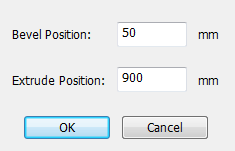
Reference You can access to the dialog or perform point handling operations with the contextual menu, which is displayed by right-clicking a control point (Win) or clicking a control point, holding down the Ctrl key (Mac).
Important TextEffector in Shade3D Basic does not show the Set Point Position dialog when double-clicking a point.
Adding a Point
Click a point on the bevel line, holding down the Ctrl key (Win) or Option key (Mac) to add a control point to the bevel line.
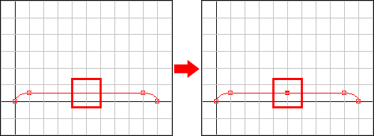
Hold down the Ctrl key (Win) or Option key (Mac) on the bevel line to show at the lower right side of the cross cursor the cross sign, which is the indication of addition of a point.
Deleting a Control Point
To delete a control point, click it, holding down the Ctrl+Shift keys (Win) or Option+Shift keys (Mac).
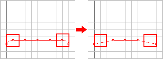
Hold down the Ctrl+Shift keys (Win) or Option+Shift keys (Mac) on the bevel line to show at the lower right side of the cross cursor the minus sign, which is the indication of deletion of a point.
Selecting Control Points
Click a control point to select the point. Keep the point selected, and then click another point, holding down the Shift key; the control points are simultaneously selected. To cancel a selected point, click it, holding down the Shift key. Alternatively, drag the pointer so that the target points are enclosed to select more than one control point.
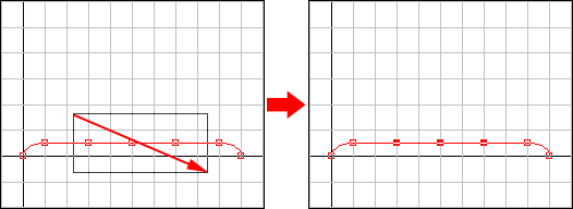
You can drag the selected points to move them all together.
Adding a Line Handle
Select a point having no line handle, and then select Add Lateral Handle in the contextual menu; a Bezier handle is added to the control point. Modify the handle to make the bevel line curved.
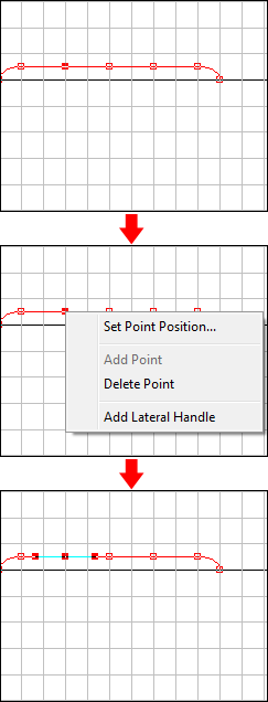
Added line handles are initially configured so that the top of the added handle is smoothed.
Editing a Handle
Selecting a control point having a line handle shows the line handle. Drag the line handle to make the bevel line curved. It is not joined to the line handle on the opposite side, and the line handle on the opposite side does not move.

When Snap is on, line handles are also snapped.
Joining Line Handles
Drag a line handle, holding down the Shift key, to set joined mode. In joined mode, the line handles on both ends and pointer are aligned and handled, keeping the distance between the handles.

Deleting a Line Handle
To delete a line handle, click it, holding down the Ctrl+Shift keys (Win) or Option+Shift keys (Mac).

Reconfiguring a Deleted Line Handle
For a point on which the line handle on one side has been deleted, drag the remaining line handle, holding down the Shift key, to reconfigure the line handle on the other side. The operation is equivalent to that in joined mode.

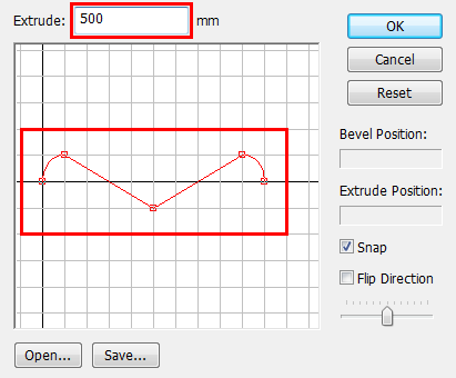
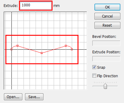
Change of the value of Extrude and the Bevel Line
When the value of Extrude is changed, the Extrude Position value (horizontal position of the bevel line) is automatically adjusted to the value, but the Bevel Position (vertical position of the bevel line) is not adjusted. Therefore, the proportional ratio of the bevel line changes on a change of the value of Extrude.
| Bevel Settings |
|---|
|
| Bevel Settings |
|---|
|