Using RoomPlanner
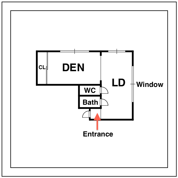
The following floor plan of a small Japanese apartment will be used as an example of how to use RoomPlanner.
Starting RoomPlanner
- Select View > RoomPlanner . to open the RoomPlanner palette.

-
RoomPlanner 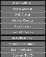
- Click the Basic Settings button on the palette to display the RoomPlanner Basic Settings dialog box. In this dialog box, enter values for the construction site and the building site. With RoomPlanner, this building site is called "HomeBase."
The area for the construction site must be larger than the building site. You can specify a value for the Tatami size fieliving-dining room under the Size Setting label. The Degree fieliving-dining room under the Direction Settings group box allows you to specify the orientation of direction based on the angle.
NoteRefer to the Reference section below for more information.
- When you click the OK button after entering all necessary values, the rectangular areas for the construction site and the building site appear in the top view. With the RoomPlanner plug-in, all modeling tasks shouliving-dining room be performed in the top view.
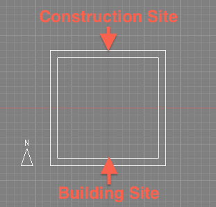

The areas for the construction and building sites are created in the top view.
NoteRooms can be created only inside the area for the building site.
Creating Rooms
- Click the Room Creator button on the RoomPlanner palette to draw a room in the top view.
RoomPlanner 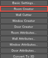
- Drag the mouse within the HomeBase area in the top view to create a rectangle.
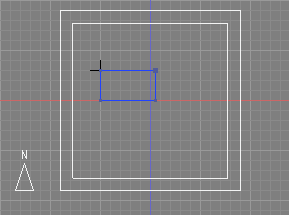
- A room is created and the Room Creator dialog box appears.
Room Creator - 9.1 Tatami 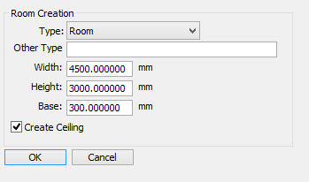
Select a type for the created room from the Type pulldown menu under the Room Creation label . Specify other parameters such as the width and height of the room. The title bar of the Room Creator dialog box shows the size of the created room, as measured in Japanese Tatami, or mats. - To change the size of a room, select the room you wish to change and click the Room Attribute button on the RoomPlanner palette. The Room Creator dialog box appears and you can alter the room size by entering appropriate values.
RoomPlanner 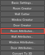
Room Creator - 8.0 Tatami 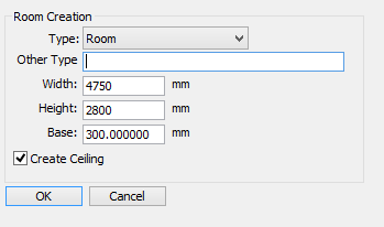
NoteWith RoomPlanner, operations using control points are not possible in the top view.
In this example, it is assumed that the Western Style Room option is selected from the Type menu and 4750mm and 2800mm are entered for the width and height in order to create an 8 Tatami room. Other properties are left as defaults.
IMPORTANTWhen the desired type of room is not found in the Type pull-down menu, you can enter a custom type name in the Other Type textbox. The Type pull-down menu is ignored when a name is entered in the Other Type textbox. This name is reflected on the Home part.
- Create another room . Click the Room Creator button and position the cursor within the HomeBase (building site) in the top view. This room shoulivingdining room be drawn so that it is adjacent to the Western Style Room just created. The size shoulivingdining room be set to 2800mm in width (horizontal dimension in Top view) and 5900mm in height (vertical dimension).
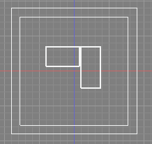
- Choose the Living-dining room option (Living-Dining) from the Type pull-down menu in the Room Creator dialog box.
- Once the Living-dining room room is created, draw and arrange other rooms and areas, such as an entrance, toilet and closet, in a similar manner.
Deleting a Wall
- Remove the wall between the two rooms to make one suite of rooms. Select the Wall Cutter option on the RoomPlanner palette. Position the cursor on a point on a wall from where you will start removing and drag the mouse along the wall.
RoomPlanner 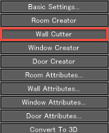
- In this example you will remove the wall between the Entrance and the Living-dining room. You will also remove the wall between the Western Style Room and the Living-dining room in a similar manner.
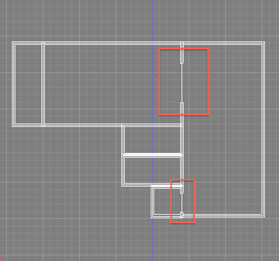
IMPORTANT To cancel the deletion of a wall, select the room that contains the deleted wall in the Home group box of the Browser window, or click the room containing the deleted wall in the top view to activate the target room. Click the Wall Attribute button on the RoomPlanner palette to display the Wall Cutter dialog box. Enter "0" in the Size textbox and click the OK button. This is the only way to cancel the deletion of a wall in the current version.
Creating Doors
- Click the Door Creator button on the RoomPlanner palette and add doors to the Entrance, Toilet and Bathroom.
- To add a door to the Entrance, position the cursor at a point on the wall of the Entrance and drag along the wall. In a similar fashion, you can create a door to the Toilet and Bathroom.
RoomPlanner 
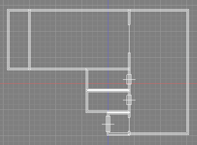
- To change the size of the door you created, select the room that contains the door in the Home group box of the Browser window, or click the room containing the door in the top view to activate the target room. Then click the Door Attribute button on the RoomPlanner palette to display the Door dialog box. Enter an appropriate value in the Size textbox to change the size of the door.
Door 
Door 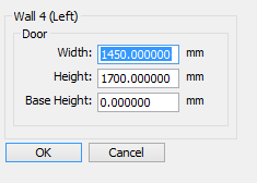
NoteTo delete the door, enter "0" in the Size textbox in the Door dialog box. This is the only way to remove a door in the current version.
Converting to 3D
The layout design you have created in the top view is displayed as a 2D (two-dimensional plane) image, even when it is rendered in the perspective view.
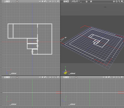
- To convert the 2D image into 3D (threedimensional model), click the Convert to 3D button on the RoomPlanner palette.
RoomPlanner 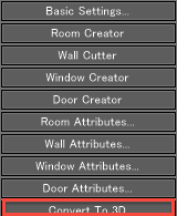
- The current 2D image is converted into 3D.
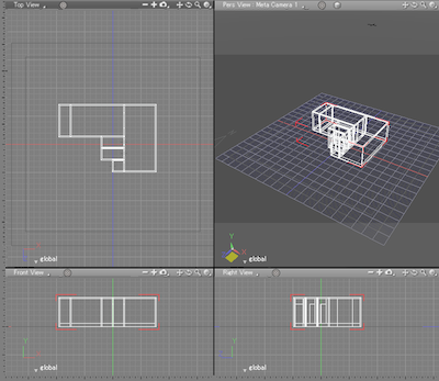
IMPORTANTIt is still possible to add rooms after the image has been converted to 3D. Once the conversion is done, a 3D Home section is created below the Home section in the Browser. The names of the created 3D image parts are displayed in this section. When you make additions or modifications to the 2D image, those changes will be automatically reflected in the 3D image.
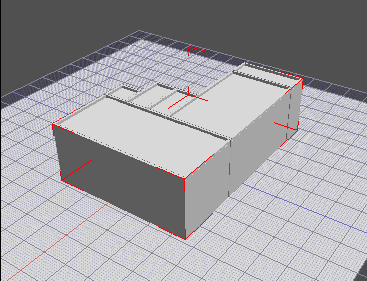
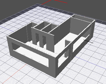
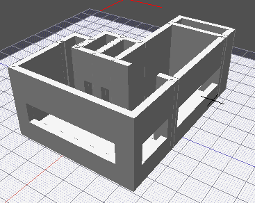
An image in which quick rendering (Display Mode > Shad- ing) has been applied in the perspective view.
Creating Windows
- Next, let's add a window to this floor plan. Select the Window Creator option from the RoomPlanner palette. Position the cursor at a point on a wall at which you want to draw a window, and drag along the wall to create it.
RoomPlanner 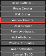
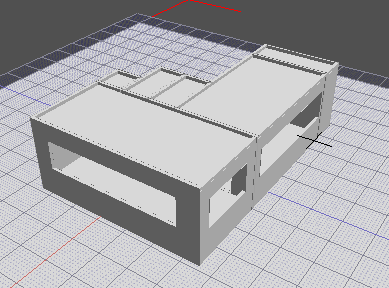
In the perspective view, the window is rendered in 3D. - To change the size of the window you created, select the room that contains the window in the Home section of the Browser window, or click the room containing the window in the top view to activate the target room. Then click the Window Attribute button in the RoomPlanner palette to display the Window dialog box. Enter an appropriate value in the Size textbox to change the width of the window.
RoomPlanner 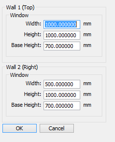
NoteTo delete the window, enter "0" in the Size textbox in the Window dialog box. This is the only way to remove an existing window.
Height of the Entrance Floor
In general, the height of the Entrance floor is lower than the floors of other rooms . With RoomPlanner, the height of the Entrance floor is set to 300mm by default, the same de- fault value for the floors of other rooms and compartments. This height can be changed using the dialog box for editing an Entrance object.
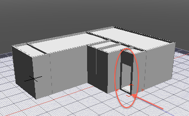
The Entrance floor height has been changed to 100mm
Removing Ceilings
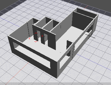
Now let's switch off the Create Ceiling check box.
- Select one of the rooms displayed in the Home section of the Browser window. Click the Room Attribute button on the RoomPlanner palette to display the Room Creator dialog box. Click the Create Ceiling check box to deselect it and click the OK button. Repeat the same procedure for the other rooms.
By removing ceilings, the details of the building become more visible in the 3D view.
Modifying Basic Settings
The basic settings of a floor plan designed with RoomPlanner, such as the Wall Thickness and Ceiling Height, can be modified even after the plan has been converted to 3D.
- Click the Basic Settings but ton on the RoomPlanner palette to display the RoomPlanner Basic Settings dialog box.
- Enter appropriate values in the Wall Thickness and Ceiling Height textboxes to change these basic properties.
In this example, the values for the Wall Thickness and Ceiling Height are changed to 300mm and 3500mm, respectively.
RoomPlanner 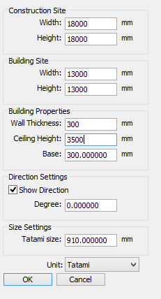
The 3D image changes as shown below after the Wall Thickness and Ceiling Height values have been updated.
