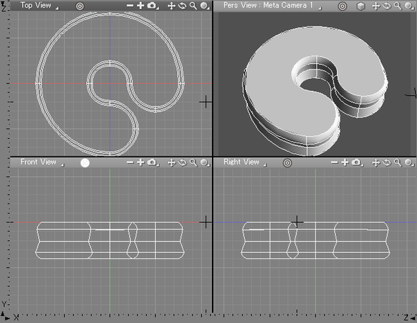
Bevel Reference
Bevel Dialog Box
| Bevel |
|---|
|
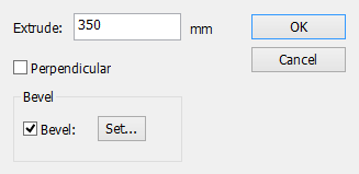
- Extrude Text Box
- Shows the distance you dragged in the Figure window. This numerical value can be edited.
Note If you enter a value, the distance dragged within the Figure window is ignored.
- Perpendicular Checkbox
- Forces the extrusion to be perpendicular to the plane of the selected line object (parallel to the normal).
- When selected, the direction you dragged in the Figure Window only determines which side the object is extruded to. The line object's plane is determined by the coordinates of its first three anchor points.
- Bevel Checkbox
- Adds bevels to the extrusion.
- Set... Button
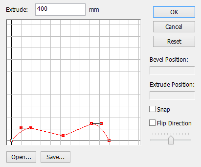
- If you click the Set... button, the Bevel Setting dialog box is displayed, allowing you to modify the bevel lines (For more information on the Bevel Setting dialog box, refer to the section on the TextEffector).
Bevel Attribute Settings
With Bevel, a created extruded object (with or without bevels) includes the parameter settings used for its creation as custom information. These parameter settings can be edited later.
Setting Bevel Attributes
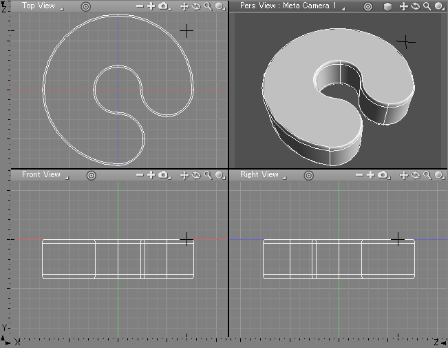
- To configure the settings, select the entire extruded object created with Bevel.
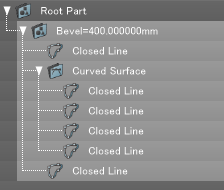
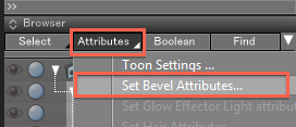
- Select Bevel Attribute Settings... from the Attributes button in the Browser.
- The Set Bevel Attributes dialog box opens.
Set Bevel Attributes 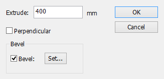
The settings of parameters in the Set Bevel Attribute dialog box and the Bevel Setting dialog box are the same as those used for the creation of the selected extruded part. You can specify or change these parameter values in the same manner as when you created the extruded object. - Click the Settings button next to the Bevel checkbox to open the Bevel Settings dialog box.
Bevel Settings 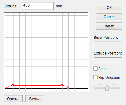
- After adjusting the settings as desired, click OK and then close the Set Bevel Attributes dialog box to apply the changes to the extruded solid.
The attributes of extruded objects, both with and without bevels, are cross-platform.
Bevel Settings 