Auto Smooth Reference
Auto Smooth (NURBS) Dialog
| Auto Smooth (NURBS) |
|---|
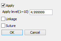
|
- Apply Checkbox
- If this checkbox is selected, Auto Smooth is applied, depending on the current selection.
- Apply Level (1<10) Text Box
- Use this text box to specify the level of corner roundness, in the range of 1 to 10.
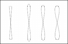
- Linkage Checkbox
- This checkbox is useful for applying Auto Smooth effects to multiple contiguous line objects or curved surfaces.
If this checkbox is selected, Auto Smooth will be applied to the multiple contiguous line objects or curved surfaces that are currently selected. When you move an affected control point, automatic smoothing is performed.
NoteMultiple contiguous line objects or curved surfaces must be connected through the control points at their ends. The linkage option is not available for objects that are separate from each other.
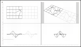
Auto Smooth (NURBS) 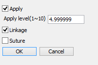
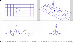
When you move a control point in one of the curved surfaces, Auto Smooth will be applied to both of them . - Suture Check Box
- Even when the linkage option is selected, moving a control point on the edges of line ob- jects or curved surfaces will not have a linking effect on the adjacent line objects or curved sur- faces .
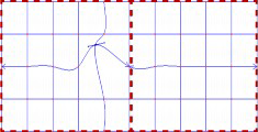
In the example above, the link action is not available by moving any control point on the dotted line.
Applying the Linkage Option to Multiple Curved Surfaces
When the linkage option is selected, arrows indicating the direction of the linkage of multiple contiguous curved surfaces are displayed on their edges. Be sure that these arrows point to the other curved surface. Otherwise, the linkage option will not be available.
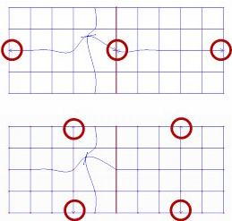
Arrows indicating the direction of connected curved surfaces.
Top: matched. Bottom: not matched.
The direction of arrows can be changed using the Switch option in the Modify tool of the Toolbox.
The linkage option also works when a curved surface is surrounded by two or three other curved surfaces. In this case also, the two arrows on the edges of the curved surface enclosed by other curved surfaces are positioned along one direction. However, the curved surfaces whose direction does not match the key curved surface can be linked by connecting those surfaces to both sides of the key surface and applying the linkage option.
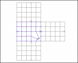
In the example above, the curved surface in the middle (in Modify mMde) is positioned in the horizontal direction. On the other hand, the direction of the curved surfaces above and below it is vertical. However, because the linkage option has been applied to these curved surfaces, they can be linked to the curved surface in the middle.