The Figure Window Display
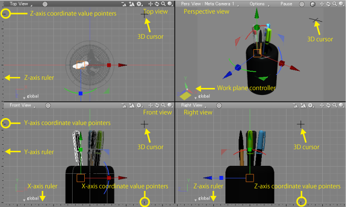
The default Figure Window is divided into four viewports.
Rulers are displayed along the left and bottom sides of the window.
By default a grid is displayed in the Top View, Front View, and Right View. (The grid can be turned off by clicking the Display pop-up menu in the top right corner of each viewport and deselecting Figure Window > Show Grid.)
The viewport and grid colors can be changed in the Preferences Dialog.
Switching Editing Modes, changing snap settings, switching work planes, using Stereo Vision, and other options are accessible from the Control Bar at the top of the Figure Window.

The Default Split View
The default Figure Window is divided into four viewports:
These three views are called the orthographic views.
Adding, editing, and viewing objects in the scene is all done in the Figure Window's viewports.
Rulers
By default the Z axis ruler is displayed to the left of the Top View (the top left viewport) and below the Right View (the bottom right viewport). The Y axis and X axis rulers are displayed to the left and bottom of the Front View (the bottom left viewport), respectively. These rulers are used to display the position of the 3D cursor. The Top View, Front View, and Right View, and rulers share the same X, Y, and Z coordinate axes.
The 3D Cursor
When moving the mouse pointer in the Figure Window, the 3D cursor, in the shape of a cross, moves in each of the viewports to show your position in 3D space. For example, moving the mouse pointer in the Top View will also move the 3D cursor in the Front, Right, and Perspective Views.
When moving the mouse pointer outside the Figure Window, the 3D cursor will stop following the mouse movement and remain fixed at some position. This position is called the "current 3D cursor position" and will be the last point clicked in the Figure Window. Many operations in Shade3D use the current 3D cursor position as the reference point.
You can also click on a ruler to set the 3D cursor position. Clicking on a ruler changes only the 3D cursor position, and will not affect other operations, such as creating objects.
The coordinates of the current 3D cursor position are displayed in the Status Bar.
Large Cursor
The 3D cursor can be expanded to reach the edge of each viewport. To switch to Large Cursor, from the Menu Bar select Figure > Large Cursor, or click the Large Cursor button on the Control Bar. Select Large Cursor again to revert back to the normal cursor.
Restricting the Movement of the 3D Cursor
For many operations in the Figure Window, you can restrict the cursor movement to multiples of 45 degrees by pressing Shift while dragging.
Sticky Mouse
To use simple clicks in place of click-and-drag operations, select Sticky Mouse in the Preferences Dialog's General tab.
With Sticky Mouse, clicking once is the equivalent to pressing down on the mouse button before dragging, and clicking a second time is the equivalent to releasing the mouse button.
For some operations a click may have a different function, in which case a slight drag may be necessary after the first click.
Figure Window Scale
Although the size of the Figure Window is restricted by the size of the monitor, the size of the 3D space within each viewport of the Figure Window has no limit. Each viewport is like a window in the literal sense, allowing you to look in at a scene of limitless size. Put another way, it is like having an incredibly large piece of paper spread out on a drawing table.
The distance between dots on the monitor can be scaled from 0.001 times to 100,000 times, which corresponds to a ratio of 1,000,000, from the minimum units of mm to the maximum units of km. This means the resolution of the scene can range from 0.001 mm to 100,000 km. Scrolling, both vertically and horizontally, can also be considered practically limitless. Scrolling around the scene is like moving the large piece of paper around on the drawing table.
Changing the scale of the Figure Window can be done in one of several ways:
Navigation Tool Zoom Icon
The Navigation Tool in the upper-right corner of each viewport has a magnifying glass icon. Click on this icon and drag up or to the right to zoom in, and down or to the left to zoom out. In Perspective View, the Zoom icon moves the Eye Point forward or backward.
![]()
Navigation Tool Zoom Out and Zoom In Icons
The Navigation Tool's dedicated Zoom Out and Zoom In icons make it easy to zoom the viewport with one click. Clicking the Zoom Out icon increases the scale, making objects in the scene appear smaller. Zoom In does the reverse.
![]()
Clicking Zoom In three times in turn will increase the scale by 2, by 2 again, and then by 2.5, for a total of a tenfold increase. The converse is true for Zoom Out.
Holding down Ctrl or Z (Win) or Option (Mac) while using the Zoom Out and Zoom In icons will center the zoom on the 3D cursor.
View Operations Menu Zoom In/Out Modes
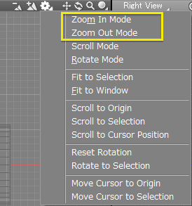
From the Zoom Operations pop-up menu (the gear icon), selecting Zoom In Mode will change the mouse pointer to the zoom in pointer. Click in the Figure Window to zoom in, centered on the clicked position.
Also from the Zoom Operations pop-up menu, selecting Zoom Out Mode will change the mouse pointer to the zoom out pointer. Click in the Figure Window to zoom out, centered on the clicked position.

From the Figure Menu
Selecting Zoom In Mode or Zoom Out Mode from the Figure Menu achieves the same effect as the Navigation Tool buttons.
Note When using the mouse wheel, zooming is not centered on the 3D cursor.
Using the Keyboard
To zoom out using the keyboard, hold Space + Ctrl or Z (Win) or Space + Option (Mac). The mouse pointer changes to the zoom out icon. Click in the Figure Window to zoom out, centered on the clicked position.
To zoom in using the keyboard, hold Space + X (Win) or Space + Command (Mac). The mouse pointer changes to the zoom in icon. Click in the Figure Window to zoom in, centered on the clicked position.
Using the Mouse Wheel
Move the mouse wheel in the down direction to zoom out, or in the up direction to zoom in.
Note When using the mouse wheel, zooming is not centered on the 3D cursor.
Scrolling the View
Click and drag the Scroll icon in the upper right corner of a viewport to scroll in the direction you drag.
![]()
If you hold down Space, the mouse pointer changes to a hand icon, and you can click and drag in a viewport to scroll.
Rotating the View
Click and drag the Rotate icon in the upper right corner of a viewport to rotate the view in the direction you drag. In Perspective View, the camera eye point rotates.
![]()
If you hold down Space + Shift, the mouse pointer changes to a hand icon with a curved arrow, and you can click and drag in a viewport to rotate the view.
In any view other than Perspective View, clicking the Rotate icon will reset the rotation.
Fit to Selection
Click the Fit button in any viewport to zoom and center the view on the currently selected object(s). In Perspective View, clicking the Fit button will zoom and center the selected object(s) in the camera's field of view.
![]()
Note Fit to Selection for Perspective View is also available in the Camera Window, in the Set & Link group.
In the orthographic views, Fit to Selection is also available from the View Operations pop-up menu.
Fit to Window
Select Figure > Fit to Window to zoom the view so that all objects fit within each viewport. This command is also accessible from the View Operations pop-up menu in each viewport.
Note The objects are centered in each viewport. Objects hidden in the Figure Window are ignored when using Fit to Window.
Parallel Projection
Click the Parallel Projection icon in the Perspective View to switch the view to Parallel Projection mode. Click the icon again to switch back.
![]()
Changing the Viewport Layout
Select Figure > Viewport Layout from the main menu or click the Viewport Layout button on the Control Bar to switch between different viewport layouts.
Resizing Viewports
When using multiple viewports in the Figure Window, you can move the dividing line between viewports to resize them.
When the mouse pointer is over a dividing line between viewports it changes to a double-headed arrow, showing they can be resized. Drag the dividing line to resize the viewports, changing the ratio of their size.
Switching Work Planes
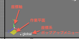
The Work Plane Controller in the bottom left corner of Perspective View can be used to switch between different work planes.

Moving the mouse pointer over one of the possible work planes will highlight that plane. Click to switch to that work plane.
Click in the center of the work plane to switch to the screen plane, parallel to Perspective View.
Locking the Work Plane
Click the current work plane (displayed in yellow) to lock it. It will change to green. Click it again to unlock the work plane.
Switching to an Axial Projection
Clicking on the X, Y, or Z axis shown in the Work Plane Controller will switch to a plane orthogonal to that axis. To switch back, click the "global/local" pop-up menu in the Work Plane Controller and select Camera : Reset to reset the camera. Alternatively, from the same menu select << to undo the last camera change.
Hold Shift while clicking an axis to switch to the view from the negative direction.