Curves
Use the Curve tool to create a NURBS curve. The mouse pointer can be used, or numbers can be input directly in the Tool Parameters.
| Basic | Standard | Professional |
|---|---|---|
| - | - | O |
Usage
- In CAD Mode, select Curve from the Toolbox's CAD creation tools.
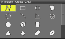
- Click in the Figure Window to create the curve. The length and angles of the curve are shown as you create each segment.

- Click the Apply button in the Tool Parameters to confirm creation of the object.

Tool Parameters
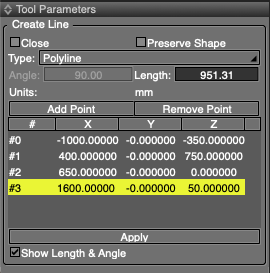
- Close
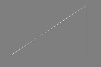
- When selected, clicking Apply will connect the end points of the line, creating a closed line.
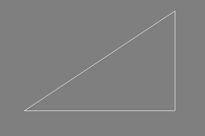
- When unselected, the end points are not connected, leaving it an open line.
- Preserve Shape
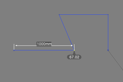
- When changing the length or angle of a line segment, this option preserves the shape of latter line segments. In the figure below, deselecting Preserve Shape before changing the length of the first line segment results in a changed angle between the first and second line segments.
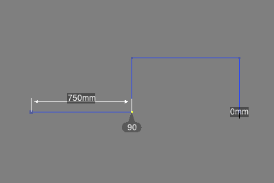
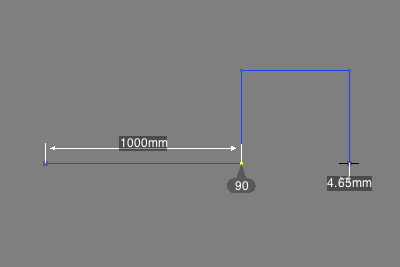
- If Preserve Shape is unselected, changing the length or angle of a line segment will affect the relative position of latter points on the line. In the figure below, deselecting Preserve Shape before changing the length of the first line segment results in a changed angle between the first and second line segments.

- Type
- Specifies the type of NURBS curve to create, either Polyline or Bezier.
- Polyline
- Creates the curve using straight line segments.
- Bezier
- Creates the curve with either straight line segments or curves using tangent handles, similar to a Bezier curve.


- Angle
- The angle between the line segments before and after the selected point. Click in the text box to edit the value.
- Length
- The length of the line segment connecting the selected point with the previous point. Click in the text box to edit the value.
- Add Point
- Adds a new point immediately after the currently selected point in the list. The new point is added to the default location of (0, 0, 0).
- Remove Point
- Deletes the currently selected point in the list.
- List of Point Coordinates
- Displays the XYZ coordinates of each point on the line being created. Click in a text box to edit its value.
- Multiple points in the list can also be selected in order to change coordinate values for all of them at once.
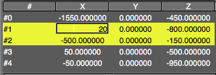
- In the figure below, the second (#1) and third (#2) points are selected.
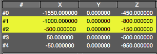
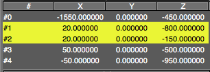
- Double-click on one of the coordinate text boxes to edit that coordinate for each point. In the figure below, the X coordinate of the second point has been changed to 20.
- Press Enter (Win) or Return (Mac) to change the coordinate value for every selected point.
- Apply
- Confirms the curve creation.
- Show Length & Angle
- Displays the length and angle of each line segment in the Figure Window when creating the line.
Note Available in Shade3D Professional.