Usage
The 3D Printing Assistant can be accessed in three ways.
From the Menu Bar
- Select View > 3D Printing Assistant.
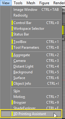
- The 3D Printing Assistant is displayed.
3D Printing Assistant 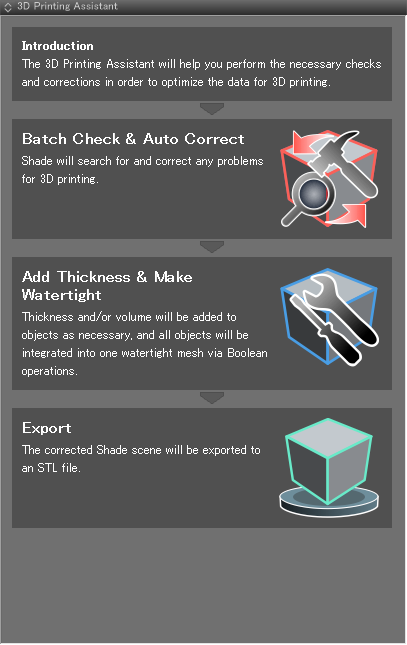
- Entering Check Mode automatically switches to the 3D Printing workspace.
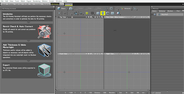
From the Workspace Selector
- Select 3D Printing from the Workspace Selector.

- Shade switches to the 3D Printing workspace, and the 3D Printing Assistant opens automatically.
From the Control Bar
- Click the 3D Printing Assistant button on the Control Bar.

- The 3D Printing Assistant is displayed.
- Entering Check Mode automatically switches to the 3D Printing workspace.
The 3D Printing Workspace
Most errors that cause problems for 3D printing include inconsistent surface normals, shapes with no thickness, and gaps between faces. These factors determine whether the model is "watertight."
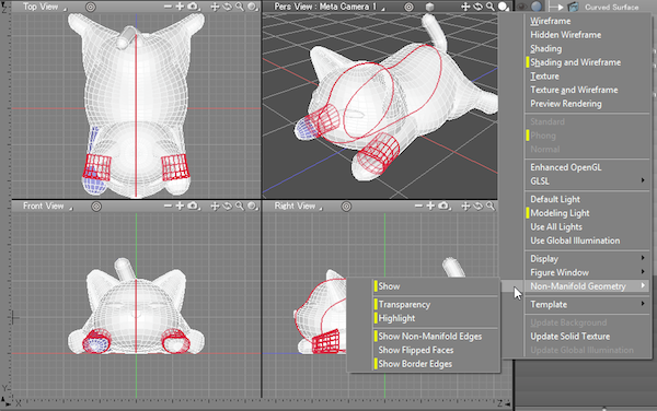
The 3D Printing Workspace is set up to make it easier to see these problems and correct them. The Figure Window display mode is set to Shading + Wireframe, flipped faces are displayed in periwinkle blue, border edges (connected to only one face) and non-manifold edges (connected to more than two faces) are displayed in red. Border edges behind other shapes (which would normally hide them) are displayed through intervening shapes so as to make them easy to find.
All of these settings can be turned on or off from the Figure Window's View Display pop-up menu, or from the Figure menu (Figure > All Viewports > Display and Figure > All Viewports > Non-Manifold Geometry).
The Top Page
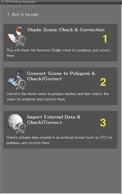
The top page presents you with three options: Batch Check & Auto Correct, Add Thickness & Make Watertight, and Export.
- 1: Opens the Batch Check & Auto Correct page for checking the scene for problems and correcting them automatically. Shade switches to the 3D Printing workspace.
- 2: Opens the Add Thickness & Make Watertight page. Shade switches to the 3D Printing workspace.
- 3: Opens the Export page. Shade switches to the 3D Printing workspace.
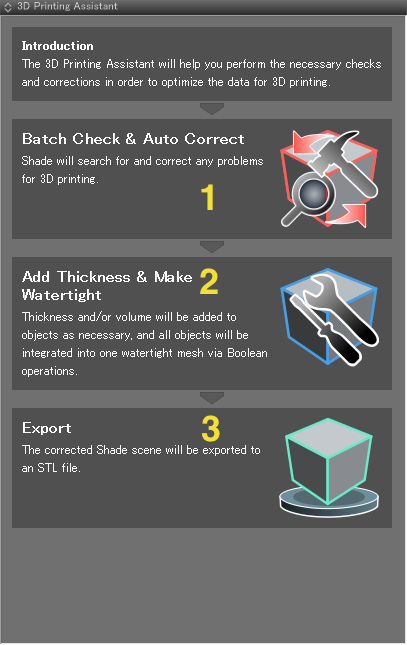
The simplest workflow is to start by checking for errors using Batch Check & Auto Correct, followed by applying Add Thickness and Make Watertight to corrected scenes, and finally exporting the model to STL format using Export.
The Batch Check & Auto Correct Page
This page is displayed when Batch Check & Auto Correct is selected from the top page.
Error checking is done for polygon meshes. In some cases, a Shade scene may contain spheres, disks, curved surfaces or other shapes that are not polygon meshes. Other shapes, such as link objects, mirrored objects, path replicators, surface replicators, joints, and so on, have no physical substance. Choose between the first and second options (Shade Scene Check & Correction and Convert Scene to Polygons & Check/Correct) depending on how you wish to deal with non-polygon shapes in the scene.
- 1: Check/Correct Shade Scene
Select to open the Batch Check & Auto Correct page and check the current scene for errors automatically.
Non-polygon shapes and shapes without physical substance should be converted to polygon meshes by hand or deleted.
Advantages When converting to polygon meshes, the level of subdivision can be specified individually for each shape.
A minimum number of polygons can be worked with until the last steps.
The Browser hierarchy does not change, making organization easier.Disadvantages The amount of work to do manually and the possibility of conversion mistakes increases. - 2: Convert Scene to Polygons & Check/Correct
Select to export the current scene as STL format internally and re-import the data as a new scene. (A confirmation dialog is displayed.)
By temporarily converting the scene elements to STL format and then importing the data back in as a new scene, all elements can be converted to polygon meshes at once.
Afterwards the Batch Check & Auto Correct page is displayed to check the scene for errors automatically.
Advantages Because everything in the scene is converted to polygon meshes at once, no manual conversions need to be done and conversion mistakes are not a problem. Disadvantages The original Browser hierarchy is lost, making it more difficult to understand the organization of the scene.
All shapes are subdivided using the same level of subdivision, meaning the subdivision of individual shapes cannot be specified. - 3: Import External Polygon Data & Check/Correct
Loads external polygon data from another 3D tool and checks them for errors.
Select to open a dialog allowing you to select a file in an external format. After selecting a file, the Batch Check & Auto Correct page is displayed to check the scene for errors automatically.
The Menu Bar
Use the 3D Printing Assistant menu bar to navigate between pages. When navigating to a different page, the top of the page is displayed.
 Opens the Batch Check & Auto Correct page.
  Opens the Batch Check & Itemized Correction page.
  Opens the Add Thickness & Make Watertight page.
  Opens the Export page.
  Opens the previous page. (When opening the More Info page, the top of the page is always displayed.)
 Opens the next page. (When opening the More Info page, the top of the page is always displayed.)
 This icon indicates there is no page to open.
  Returns to the top page.
  Exports the current scene to the specified folder. The file name will have the time stamp (yy, mm, dd, hh, mm, ss) followed by "bak.shd." (e.g., a file exported on March 9, 2014 at 12:45 and 28 seconds would have the file name "140309124528bak.shd."
 Opens the More Info page.

Batch Check & Auto Correct
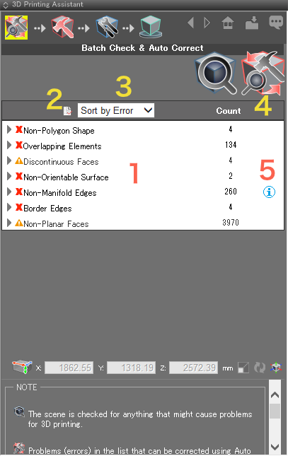
Checks all the objects in the current scene for problems (errors) at once, and performs Auto Correct.
Auto Correct fixes errors that do not require you to choose a particular correction process (such as overlapping elements and inconsistent normals). Errors that require you to make a choice (such as non-polygon objects, border edges, and non-planar faces) must be fixed on the Batch Check & Itemized Correction page.
 Checks for errors and displays them in the table below.
  Performs Auto Correct on the errors listed in the table, and displays the updated results.
 - 1: Displays the problem areas found. Clicking an item (error) will center the problem area in the Figure Window.
- 2: Exports the check log to a file.
- 3: Choose to sort the table by error or shape type.
"Sort by Error" displays a list of the errors by type (non-polygon shapes, border edges, non-planar faces, and so on). Opening each item (by clicking the arrow) reveals a list of the shape names.
"Sort by Shape" displays a list of the errors by shape type (polygon mesh, non-polygon shapes, and so on). Opening each shape type (by clicking the arrow) reveals a list of the errors.
 - 4: Shows the number of each error found.
- 5: The
 icon appears next to non-manifold edges and internal faces. Clicking it will open a page in the default browser describing the error and how to correct it. If Auto Correct finds any shapes with non-manifold edges, a dialog appears asking whether you wish to separate all shapes connected to non-manifold edges.
Batch Check & Itemized Correction Page
Checks all the shapes in the current scene for errors at once, and allows you to correct problems individually.
Each item (error) in the table can be dealt with individually. Errors that require you to choose a correction process cannot be fixed with Auto Correct, and must be corrected here.
When checking for errors, choose to check the whole scene, selected shapes only, visible shapes only, rendered shapes only, or both visible and rendered shapes.
 Checks for errors and displays them in the table below.
  Corrects all the errors listed in the table for which a correction process is specified. The table is then updated with the results.
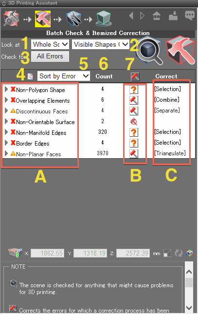
 - 1: Choose to search for errors in either the whole scene or only selected shapes.
- 2: Choose to search for errors in visible shapes, rendered shapes, or both.
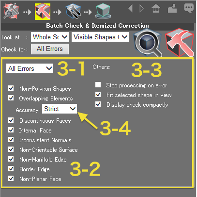
- 3: Choose to perform a comprehensive check, a simple check, or specify exactly which errors to search for. Click this button to open the item (error) options.
- 3-1: Select either All Errors (all problem types are looked for) or Basic Errors (only non-polygon shapes, overlapping elements, inconsistent normals, and border edges are looked for). Selecting other combinations of errors will display Custom in this menu.
- 3-2: Select the items (error types) to check for.
- 3-3: Select other options.
- 3-4: Specify the precision used when checking for overlapping elements. Choose either Strict or Relaxed.
- 4: Exports the check log to a file.
- 5: Choose to sort the table by error or shape type.
"Sort by Error" displays a list of the errors by type (non-polygon shapes, border edges, non-planar faces, and so on). Opening each item reveals a list of the shape names.
"Sort by Shape" displays a list of the errors by shape type (polygon mesh, non-polygon shapes, and so on). Opening each shape type reveals a list of the errors. - 6: Shows the number of each error found.
- 7: Corrects all the errors listed in the table for which a correction process is specified.
 This is identical to
 - A: Errors that require correcting are marked with
 while a warning is indicated by the
  icon.
icon.
Clicking an item (error) will center the problem area in the Figure Window.
Clicking the arrow on the left will show the individual errors or shape types.
 - B: If a correction process has not been selected for a particular error, a
 button is displayed. Once a correction process has been chosen, this changes to a
  button.
Click the button to select a correction process or choose to leave the item as-is.
 - C: Selects a correction process. Merge, Subdivide, Remove, Triangulate, and some other processes have no further options.
Note The above settings are saved for the next time the check is run.
Differences Between Auto Correct and Itemized Correction
For example, if overlapping vertices are combined (merged) manually or using Itemized Correction, overlapping faces or non-manifold edges will result. Separating those will again result in overlapping elements.
When Auto Correct corrects each individual problem, it optimizes the results for that type of error.
On the other hand, Itemized Correction displays multiple possible correction processes for errors that cannot be fixed with Auto Correct, allowing you to choose which method to use.
Errors leftover by Auto Correct can be corrected on the Itemized Correction page, after which Auto Correct can be run again. By going back and forth between Auto Correct and Itemized Correction, all errors can be found and corrected efficiently.
The Scene Tool
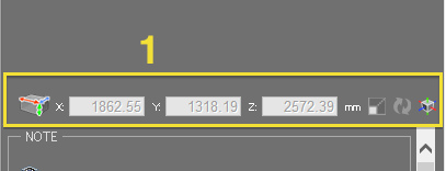
The Scene Tool is used to uniformly increase or decrease the outside dimensions of the scene, and to move the position of the origin. The Scene Tool is displayed on the Batch Check & Auto Correct page and Batch Check & Itemized Correction page.
- 1: Displays the outside dimensions of the current scene. If the scene has been modified, click the
 button to get the updated dimensions.
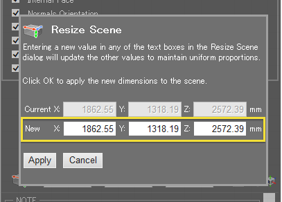
  The button opens the Resize Scene dialog, allowing you to uniformly increase or decrease the dimensions of the scene as a whole.
After entering a new value in any of the text boxes in the Resize Scene dialog, the other values will automatically update to reflect the change.
Click the Apply button to apply the changes to the scene. This button moves the origin of the scene to the center of the bounding box that marks the boundaries of the scene.
About Errors and Correction Methods
The following errors ( ) and warnings (
 ) indicate shapes or elements in the scene that may not come out properly when 3D printing, or may not import properly using the 3D printer utility software.
 Non-polygon shape (error)
 Overlapping elements (vertices, faces) (error)
 Discontinuous faces (warning)
 Internal face (error)
 Inconsistent normals (error)
 Non-orientable surface (error)
 Non-manifold edge (error)
 Border edge (error)
 Non-planar face (warning)
An overview of each error ( ) and warning (
 ) is explained below, along with the correction processes available on the Itemized Correction page.
 Non-polygon shape (error)
To correct: Convert the shapes to polygons.
 Overlapping elements (vertices, faces) (error)
To correct: Combine (merge) the vertices or faces so they will no longer overlap.
 Discontinuous faces (warning)
To correct: Separate each group of discontinuous faces as a new polygon mesh, or combine into a single watertight mesh.
 Internal face (error)
To correct: Delete the internal face.
 Inconsistent normals (error)
To correct: Unify the normals so that they all face the same direction (inwards or outwards).
 Non-orientable surface (error)
To correct: This must be corrected manually. The model must have definable front and back surfaces.
 Non-manifold edge (error)
To correct: Separate the faces from the non-manifold edge so that each has a defined front and back. Thickness must also be added to the separated faces. Alternatively, the non-manifold edges can be deleted, but this will also remove the connected faces, so all of this must be done manually.
 Border edge (error)
To correct: Either fill the hole created by the border edges or add thickness to give the edges depth.
 Non-planar face (warning)
Warning Even if one of these errors remains, sending the data to a 3D printer will not necessarily always result in an error. It depends on the 3D printer, the 3D printer's utility software, and/or the 3D printing center.
Handling Linked Shapes
When checking Shade scenes for errors, care must be taken regarding linked shapes.
It is also possible to realize the mirrored shape or convert all shapes in the scene to polygons beforehand.
Exporting the shapes as-is will convert them to polygons, but they will not be made "watertight."
Completing the Correction Stage
Use the following conditions as guidelines when deciding whether or not you are finished correcting errors using the 3D Printing Assistant:
(This condition does not apply when exporting multiple models for 3D printing.)
Add Thickness and Make Watertight Pages
Add thickness to the selected shape and make it "watertight" using Boolean operations.
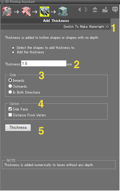
- 1: Opens the Make Watertight page.
- 2: Enter a value in mm for the thickness to add.
- 3: Select Inwards, Outwards, or In Both Directions for the direction in which to add thickness.
- 4: Select whether to measure the thickness from the side, or from the vertices.
- 5: Applies the thickness.
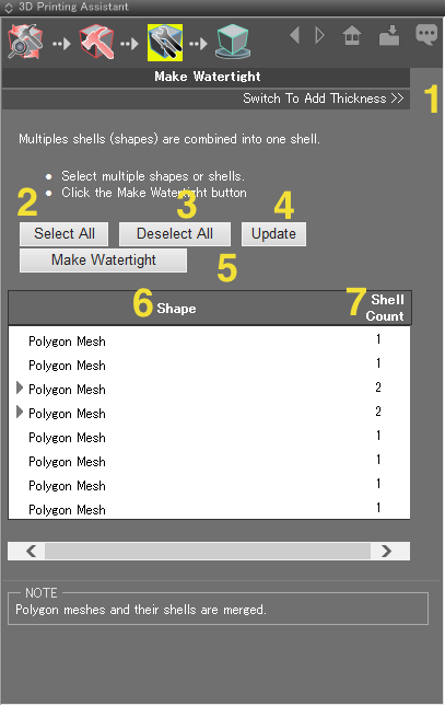
- 1: Opens the Add Thickness page.
- 2: Selects all the shapes/shells in the table.
- 3: Deselects the items in the table.
- 4: Updates the items in the table.
- 5: Integrates all the shapes into one polygon mesh so they are "watertight."
- 6: Displays the shapes and shells.
- 7: Displays the number of shells of each shape.
Export Page
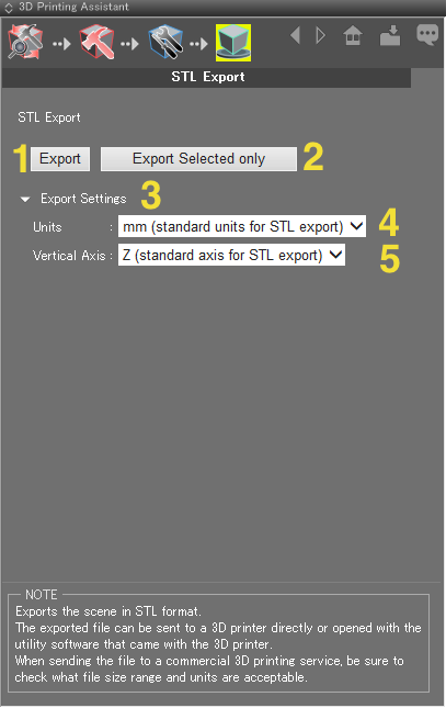
Exports the current scene, or the selected shapes, in STL format.
- 1: Opens a file dialog for exporting the whole scene in STL format.
- 2: Opens a file dialog for exporting only the shapes selected in the Browser.
- 3: Click here to display options for specifying the units and vertical axis.
- 4: Choose between mm (standard units for STL export), cm (for Maya, etc.), and inches (for 3ds max, etc.) for the units used during export.
- 5: Choose between Z (standard axis for STL export) and Y for the vertical axis used during export.
Warning Shade exports STL format in mm as standard, and OBJ format in m. Units and scale cannot be modified with the OBJ Exporter.
More Info Page
This page offers links to additional help and settings.
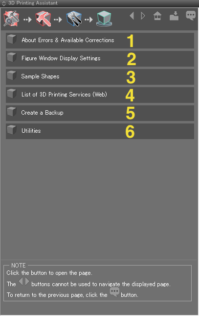
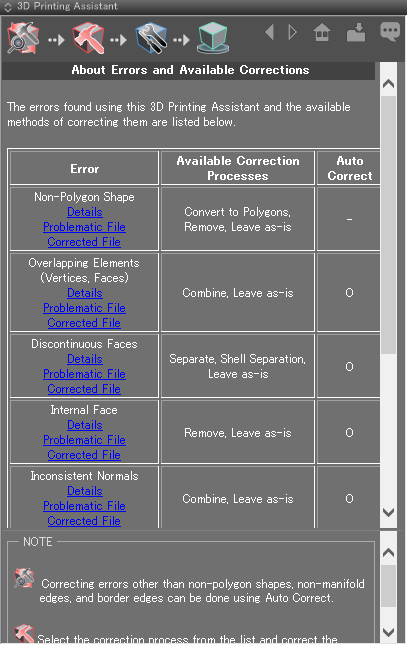
- 1: Opens a page describing the errors and corrections used by the 3D Printing Assistant.
- Details: Opens a page with details about the error.
- Problematic File: Opens a scene with the error.
- Corrected File: Opens a scene with the errors in the problematic file corrected.
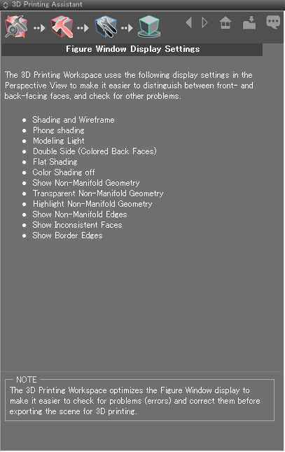
- 2: Opens a page with information on the Figure Window display settings used in the 3D Printing Workspace.
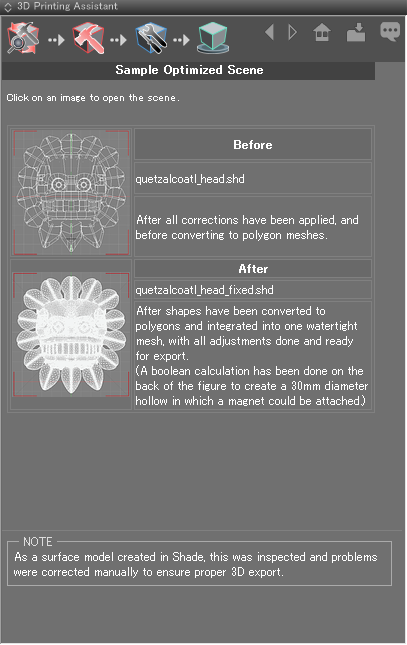
- 3: Opens a page with two sample files, one with shapes before optimizing for 3D printing, and another after optimization. Click on an image to open the scene.
- 4: Opens a webpage with a list of 3D printing services in the default web browser.
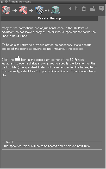
- 5: Opens a page with information on the importance of backing up your Shade scene and how to save a copy.
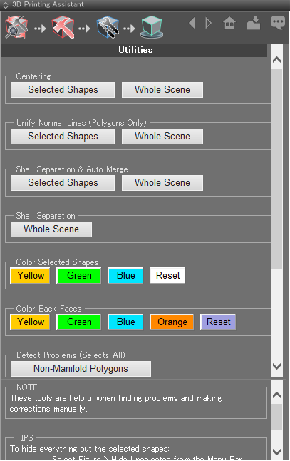
- 6: Opens a page with a number of helpful tools for correcting errors manually, including Separate Shells, Add Color to Selected Shapes, and more.
- Centering: The selected shape or whole scene is centered on the origin.
- Unify Normals (Polygons Only): Surface normals of the selected polygon mesh or whole scene are oriented outward.
- Separate Shells & Auto Merge: Separates shells of the selected polygon mesh or whole scene and merges polygons.
- Separate Shells: Separates shells of all polygon meshes in the scene.
- Color Selected Shapes: Sets the Diffuse Color of the selected shapes to yellow, green, or blue. Reset reverts the Diffuse Color to the default (white).
- Color Back Faces: Sets the color of back faces to yellow, green, blue, or orange. Reset reverts the color to the default (blue).
- Detect Errors (Selects All): Selects all shapes with target errors.
- Cleanup: Resets or removes names of shapes in the Browser and all surface attribute settings.
